Parsing the c64 Bubble Bobble Wind Currents
Background
A while ago, I managed to rip the level data and graphics from the c64 version of Bubble Bobble.
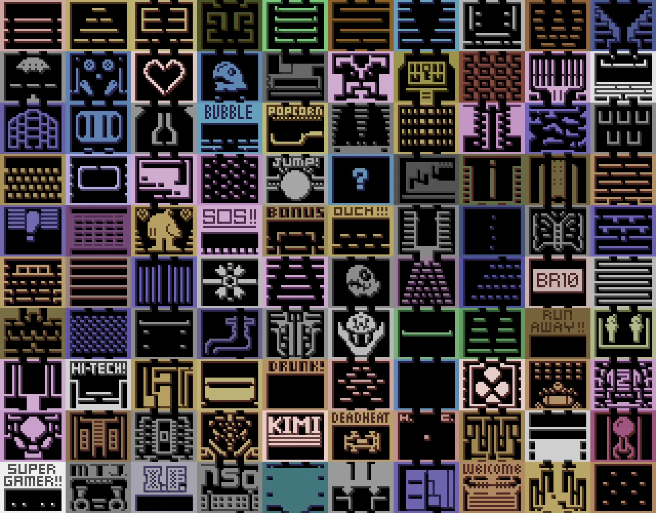
I wrote a tool in typescript that reads the data from the actual game.
It was fun to see all the levels I had played so many times, but I wanted to see if I could get more of the related data. Platform graphics and colors are stored as simple arrays, while the platform positions and monsters are increasingly complex to read.
I had to study the disassembled binary in detail to understand how the game worked. Running it in a debugger/emulator to check the values of registers at each step helped a lot.
The platforms are stored as 1-bit bitmaps where each tile in the level is represented by a single bit. The levels are 32 by 25 tiles but the top and bottom rows are not stored in the bitmap, so the bitmap is 4 bytes wide and 23 bytes tall, giving 92 bytes each.
But levels have a separate array of metadata containing among other things a flag signaling if the level is symmetric. Instead of just storing the whole bitmap, symmetric levels store only half of it and mirror it in a separate step, saving 46 bytes.
The same metadata array is used to store wether a level has extra graphics decorating the sides. The extra graphics are stored as 2 x 2 tiles of 8 bytes each giving 32 per level, and are dynamically written to the charset when loading the level. Levels without this decoration just use the single tile platform graphics instead.
The monsters instead use a single null-byte to terminate the array of monsters for each level. Pretty easy.
At this point I had noticed that the titular bubbles follows “wind currents” clearly visible in the debugger. Martin Piper has a great Bubble Bobble code analysis video on youtube if that’s your thing.
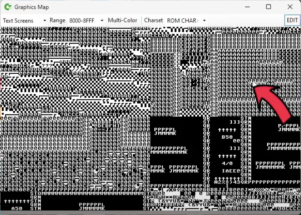
It was’t too hard to find the code responsible for decoding this data. I basically just set a debugger breakpoint when the visible memory was written to. It was also easy to find where the source data was stored. Understanding how the format worked was a lot harder. I spent a lot of hours staring at it, but since this was almost my first exposure to ASM language, I found it absolutely brain melting.
This christmas, I tried again and finally solved it. Below is the annotated 6510 disassembly. I’ll walk you through it.
The Code
********************************************************************************
* Write the bubble wind currents to a buffer at $8500. Directions are *
* clockwise, beginning with UP. *
* *
* A direction is stored for each line in the last 2 bits for each line in the *
* unpacked level bitmap. *
* *
* On top of that, a variable length list of rectangles with a direction is *
* stored at Data_WindCurrents. However, levels can instead opt to copy *
* currents from any other level. Level 2 copies from level 1. *
* *
* In the Data_WindCurrents section, each level begins with a byte where the *
* most significant bit being 1 signifies that the rest of the 7 bits is the *
* level index to copy the currents from. Otherwise, they are the number of *
* bytes used by each level, possibly 0 bytes. *
* *
* [a | bbbbbbb] *
* a: Copy-flag. *
* b: Level index or bytes to skip, depending on the copy-flag. *
* *
* The wind currents can be mirrored, in which case the left half of the level *
* is mirrored to the right, and wind direction is flipped. *
********************************************************************************
e189: UnpackWindCurrents lda $10 ;Load level index
e18b: LE18B sta $11
e18d: lda #<Data_WindCurrents ;Address $b695 stored in $02
e18f: sta $02
e191: lda #>Data_WindCurrents
e193: sta $03
e195: lda #$00
e197: sta $13
e199: lda #$8b ;Address $8b00 (unpacked level bitmap) stored in $13
e19b: sta $14
e19d: ldx $11
e19f: jsr UnpackLevel
e1a2: ldy #$00
e1a4: ldx $11 ;Loop over the levels from the index down.
e1a6: beq LE1BC ;Skip if the level is zero.
e1a8: LE1A8 lda ($02),y ;Read first byte for the current level in the loop.
e1aa: bpl LE1AE ;If the copy-flag is clear, skip.
e1ac: LE1AC lda #$01 ;...Otherwise, set reg A to 1.
e1ae: LE1AE beq LE1AC ;If the first byte was zero, set Reg A to 1.
e1b0: clc
e1b1: adc $02 ;Add reg A (the first byte or 1 if it was 0) to the
e1b3: sta $02 ;pointer, skipping that many bytes in Data_WindCurrents.
e1b5: bcc LE1B9 ;With overflow
e1b7: inc $03
e1b9: LE1B9 dex
e1ba: bne LE1A8 ;End loop level.
e1bc: LE1BC lda ($02),y ;Read first byte of the selected level.
e1be: bpl LE1C5 ;If bit 0 (copy-flag) is clear, skip to loading currents.
e1c0: and #%01111111 ;Mask out the copy-flag.
e1c2: jmp LE18B ;Reg A contains a level index. Load that levels currents instead.
e1c5: LE1C5 sta $11
e1c7: ldx #$18 ;Loop over 24 lines
e1c9: lda #$00 ;Address $8500 stored in $04. This is the unpacked wind buffer.
e1cb: sta $04
e1cd: lda #$85
e1cf: sta $05
********************************************************************************
* Read the last 2 bits off the unpacked level bitmap for each line to use as *
* wind current. The top and bottom lines get their data from the hole *
* metadata. *
********************************************************************************
e1d1: LE1D1 ldy #$03 ;Read the last byte in each bitmap line. (line[3])
e1d3: tya ;Use 0b11 (3) to mask out the bits we need.
e1d4: and ($13),y ;zp$13 pointer contains $8b00 (unpacked level bitmap)
e1d6: ldy #31 ;Loop over tiles in a line
e1d8: LE1D8 sta ($04),y ;Write the 2 bits to the wind buffer.
e1da: dey
e1db: bpl LE1D8 ;End loop row
e1dd: lda $13 ;6 lines, Add 4 (one line worth of level bitmap bytes) to zp13 pointer.
e1df: clc
e1e0: adc #$04
e1e2: sta $13
e1e4: bcc LE1E8 ;Overflow
e1e6: inc $14
e1e8: LE1E8 jsr AddDec40ToPointerAtZp04AndDex
e1eb: bpl LE1D1 ;End loop screen
********************************************************************************
* Loop over a list of rectangles to fill with a wind direction. *
* *
* Header: *
* Byte 0: *
* Bit 0: Since we came here, bit 0 must be 0. *
* Bit 1-7: Byte count for this level. *
* *
* Rectangles: *
* Byte 1: *
* Bit 0: Rectangle/symmetry-flag. *
* Set: This is a rectangle. *
* Clear: Make currents symmetric. Ignore the rest of the bits. Everything *
* up to this point is mirrored. Should probably only be done last. *
* Bit 1-2: Direction *
* Bit 3-7: Rectangle Left *
* Byte 2: *
* Bit 0-4: $05 (>>2) Rectangle Top *
* Bit 5-7: $06 Rectangle Width, bit 3-5 *
* Byte 3: *
* Bit 0-1: $06 Rectangle Width, bit 6-7 *
* *
* Bit 2: MISSING *
* *
* Bit 3-7: $07 Rectangle Height *
* *
* Horizontally: *
* Byte 1 Byte 2 Byte 3 *
* Sk. Dir. Left Top Width ? Height *
* x xx xxxxx | xxxxx xxx|xx x xxxxx *
* *
* $0b: Current byte offset into the rectangle array. *
* *
* The loop is only exited when the exact number of bytes specified by the *
* header has been used, as indicated by $0b. $0b is incremented by 3 each read *
* rectangle, or by 1 for a symmetry marker. *
********************************************************************************
e1ed: iny ;Y=0
e1ee: lda ($02),y ;Read first byte.
e1f0: beq LE188 ;If the byte count is 0, return. There's just an RTS after the branch.
e1f2: iny ;Y=1
e1f3: LE1F3 lda ($02),y
e1f5: bpl LE24C ;If A bit 0 is clear, this byte is a symmetry marker so do the
e1f7: tax ;symmetry. The symmetry section increments $0b by 1.
e1f8: and #%01100000
e1fa: asl A ;Shift out the symmetry bit.
e1fb: asl A ;3 lines: same as A >> 5
e1fc: rol A
e1fd: rol A
e1fe: sta $0a ;Wind direction
e200: LE200 txa
e201: and #%00011111
e203: sta $04 ;Rectangle left
e205: iny ;Y=2
e206: lda ($02),y
e208: tax
e209: lsr A
e20a: lsr A
e20b: and #%11111110
e20d: sta $05 ;Rectangle top
e20f: txa
e210: and #%00000111
e212: sta $06 ;Rectangle width
e214: iny ;Y=3
e215: lda ($02),y
e217: tax
e218: iny ;Y=4, First byte of the next rectangle.
e219: sty $0b ;Store the position in the rectangle array.
e21b: asl A
e21c: rol $06 ;more rectangle width
e21e: asl A
e21f: rol $06 ;more rectangle width
e221: txa
e222: and #%00011111
e224: sta $07 ;Rectangle height
e226: ldx $05
e228: lda Data_16BitMultiplesOfDec40?,x ;5 lines, Multiply $05 >> 1 by dec 40. That's the vertical offset the rectangle starts at.
e22b: clc
e22c: adc $04 ;Add the horizontal offset.
e22e: sta $04
e230: lda Data_16BitMultiplesOfDec40?+1,x
e233: adc #$85 ;Add the pointer $8500 (wind buffer) to the offset and store in zp04.
e235: sta $05
e237: ldx $07 ;Loop a rectangle of height stored in $07 +1
e239: LE239 ldy $06 ;Loop a line of the lenght stored in $06 +1
e23b: lda $0a ;Read the direction
e23d: LE23D sta ($04),y ;Write the wind direction
e23f: dey
e240: bpl LE23D ;End loop line
e242: jsr AddDec40ToPointerAtZp04AndDex ;Next line
e245: bpl LE239 ;End loop rectangle
e247: ldy $0b ;Redundant. Done after the jmp anyway.
e249: jmp LE282 ;Skip past symmetry.
********************************************************************************
* Mirror the wind to create symmetry. Copy from the left half to the right *
* half, flipping direction. *
* *
* $06: readIndex, Gores from 0 to including 15. *
* $07: writeIndex, Goes from 31 to including 16. *
********************************************************************************
e24c: LE24C iny ;Increment the position in the rectangle array?
e24d: sty $0b
e24f: lda #$00 ;Address $8500 stored in $04. This is the unpacked wind buffer.
e251: sta $04
e253: lda #$85
e255: sta $05
e257: ldx #24 ;Loop over 25 lines
e259: LE259 lda #$00 ;Initialize readIndex
e25b: sta $06
e25d: lda #31 ;Initialize writeIndex
e25f: sta $07
e261: LE261 ldy $06 ;3 lines, A = windBufferLine[readIndex] & 1; A is now 1 if the direction is left/right.
e263: lda ($04),y
e265: and #%00000001
e267: beq LE26F ;If direction is left/right
e269: lda ($04),y ;Read the direction
e26b: eor #%00000010 ;Flip left/right.
e26d: bne LE271 ;Else
e26f: LE26F lda ($04),y ;The direction is vertical, so just read the direction without modifying it.
e271: LE271 ldy $07 ;2 lines, Store the direction at writeIndex.
e273: sta ($04),y
e275: dec $07 ;--writeIndex
e277: inc $06 ;++readIndex
e279: cpy #16 ;If we just write to index 16, we are done.
e27b: bne LE261 ;End loop line
e27d: jsr AddDec40ToPointerAtZp04AndDex
e280: bpl LE259 ;End loop screen
; End symmetry
e282: LE282 ldy $0b ;Load the position in the rectangle array.
e284: cpy $11 ;The number of bytes for this level.
e286: beq LE28B ;Break loop
e288: jmp LE1F3 ;End loop rectangles
e28b: LE28B rts
e28c: AddDec40ToPointerAtZp04AndDex lda $04
e28e: clc
e28f: adc #40
e291: sta $04
e293: bcc LE297
e295: inc $05
e297: LE297 dex
e298: rts
I’m sure there are errors in my notes, but it is accurate enough that I could finally write the code to extract the currents and visualize them.
At e18d, a pointer to the wind current data block is constructed. Pointers are 16 bits, but since the MOS 6502 family are 8 bit processors, it has to be loaded and stored one byte at a time. The 6502/6510 can only use pointers if they are stored in the zero-page, the first 256 bytes of the address space. The least significant bits are stored at address $02 and the most significant bits at $03. That’s called Little Endian.
At e19f, the level platforms are unpacked. Bits of that data is also used for wind currents.
At e1a4, the code starts looping through over the levels, skipping over a specified number of bytes for each level until it stops at the selected level. The loop counter starts at the wanted level index and is decremented. That way, only one register is needed.
The number of bytes to skip is read at e1a8. The first bit says if the level even has any wind data, or if it should copy the wind from another level instead. If it has it’s own wind data, the rest of the bits says how many bytes are used. At e1b1, that number is added to the wind data pointer, skipping the level. Being a 16 bit pointer on a 8 bit processor, any overflow must be handled manually, so at e1b5, the carry-bit is checked, and the most significant half of the pointer is incremented if set.
At e1b9, the loop counter is decremented and a BNE instruction (short for “Branch if Not Equal”) is used to check if the result after decrementing was zero. If it was not zero, the branch is taken to the top of the loop where the first byte of the next level is read.
After the loop at e1bc, the first byte of the selected level is read again. As explained above, if the first bit is set, the remaining bits are the level index to copy the wind data from. If set, the byte is masked with #%01111111, discarding the first bit. At e1c2, the code then jumps to the beginning of the function, just after the level index was loaded. That makes this a recursive function that will follow any number of indirections.
If the copy-bit was not set, execution continues at e1c5, where the level platform bitmap unpacked at e19f is used. The last 2 bits of each row stores the default wind direction for each row. Those 2 bits can be used since the sides of the levels always are solid anyway. The loop goes on until e1eb.
At e1ed, the main wind data parsing begins. The Y register was used as a loop counter earlier at e1da, and ended up as -1. Therefore it is incremented to 0 and used to read the first byte. Again. Since we have come this far, that first bit must be zero, and the rest of the bits is the number of bytes used by this level.
The count may be zero, and if so we are done, so just return. Interestingly, the developer choose to reuse a random RTS instruction at address LE188 instead of adding one in this function.
At e1f2, the array index Y register is incremented again and the second byte is read. Again, the first bit is used to select between 2 different cases: Either:
-
This byte and the 2 following make up a rectangle with a wind direction to draw to the wind buffer, in which case wee keep executing the next line at e1f7.
-
Or it tells us to make the wind data loaded so far symmetric by copying the left half to the right, mirroring it and flipping the wind direction horizontally. In That case the execution branches to LE24C, where this symmetry is handled. It is possible to include multiple symmetry markers, but it wouldn’t make sense to have more than one per level.
At e1f7, we handle the rectangle. The content of the A registry is the first rectangle byte. It is copied to the X registry as well, for safe keeping. Then bit 1 and 2 are masked out with #%01100000.
At e1fa, the byte is shifted left, discarding the top bit that told us this is a rectangle. Another left shift is done, causing the upper of the 2 masked bits to be shifted out as well. But the shift instruction stores the discarded bit in the carry-flag. The following 2 ROL instructions work pretty much like left shifts, but the fresh bit added at the right end is taken from the carry-flag instead of just adding a zero. The end result is equivalent to shifting right 5 times. Yay, we saved one instruction!
At e1fe, the resulting 2-bit value is the wind direction, and is stored away for later.
At e200, the first rectangle byte is copied back to A from the X register, since there is more data in it to handle. This time it is masked with #%00011111. That’s the left position of the rectangle. It too is stored away for later.
At e205, the second rectangle byte is read. It too is copied to the X registry. It is shifted right twice and the masked with #%11111110. This is the top position of the rectangle.
Notice how the lowest bit was masked away. You’d think the byte would be shifted right one more time instead. But the code used to actually draw the rectangle to the wind buffer would need to multiply it by 2 anyway, so it is stored as twice the actual value.
At e210, the remaining 3 bits are masked with #%00000111 and stored at address $06. They are the top 3 bits of the 5 bit rectangle width. The bottom 2 bits are taken from the top bits of the last byte of the rectangle. It is done at e21b, by shifting out the top bit from the A register and ROL-ing it into the bottom of the byte at address $06 where the width was stored. That’s done twice, once for each bit.
In the middle of that, at e218, the Y register used to index the rectangle bytes is incremented and stored away in address $0b. That’s where the next rectangle will start reading from.
Finally at e222, the third rectangle byte is masked with #%00011111, giving the rectangle height.
For some reason, both the width and the height are stored as one less than the actual number. Of course zero width/height rectangles would be pretty useless in this context, and there are only 5 bits, but I don’t think it actually helps with anything.
At e226, the rectangle coordinates are loaded and at e239 a loop begins drawing the rectangle to the wind buffer. After the loop comes the symmetry code, so it is JMP-ed past.
At e282, the position in the rectangle bytes array is compared to the size allocated for this level and if they match, the function returns, otherwise the code loops back to LE1F3 to read another rectangle.
Results
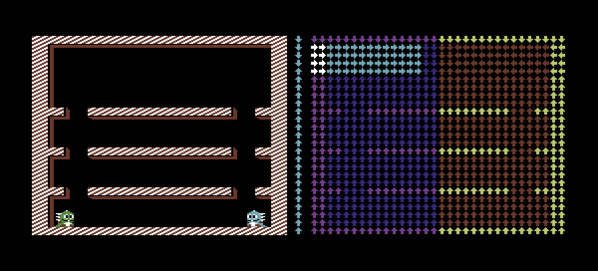
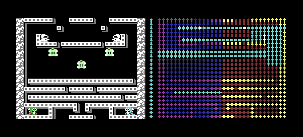
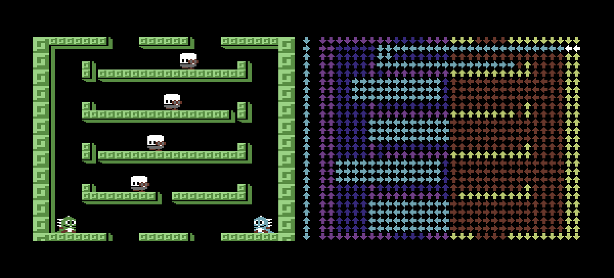
After successfully reading the wind data, I could visualize it. Here are a few examples. To the left is the level as it would look when playing the game. To the right is the wind, with arrows pointing in the direction of the current.
I color coded each tile.
- Cyan is the explicit stored data. The column just to the right of the level is the per-row default wind direction stored in the platforms bitmap. Everything else is stored as rectangles.
- White is used where Cyan overlaps a platform, just to make it easier to visually correlate the wind with the platforms.
- Dark blue is where the wind direction is determined by the per-row default direction.
- Purple is where the dark blue overlaps a platform.
- Red is where a direction has been reflected from the left side by a symmetry-marker.
- Yellow is where the red overlaps a platform.
